When discussing product life, the expression of [θ10℃ rule] is generally used, and a simple explanation can be expressed as [10℃ rule], when the ambient temperature rises by 10℃, the product life will be reduced by half; When the ambient temperature rises by 20 ° C, the product life will be reduced to a quarter. This rule can explain how the temperature affects the life of the product (failure), the opposite product reliability test, can also be used to increase the ambient temperature to accelerate the failure phenomenon, a variety of accelerated life aging tests.
Causes of failure caused by moisture:
Water vapor infiltration, polymer material depolymerization, reduced polymer bonding ability, corrosion, cavitation, wire solder joint detachment, leakage between leads, wafer and wafer bonding layer detachment, pad corrosion, metallization, or short circuit between leads. Effect of water vapor on the reliability of electronic packaging: corrosion failure, delamination and cracking, changing the properties of plastic sealing materials.
PCT failure mode for PCB:
Blister, Crack, SR de-lamination.
PCT testing of semiconductors:
PCT is mainly to test the moisture resistance of semiconductor packaging, the product to be tested is placed in a harsh temperature and humidity and pressure environment test, if the semiconductor packaging is not good, moisture will penetrate into the package along the colloidal or colloidal and wire frame interface into the package, common reasons for installation: Popcorn effect, open circuit caused by corrosion of dynamic metallized area, short circuit caused by contamination between package pins... And other related issues.
PCT reliability assessment for IC semiconductors:
DA Epoxy, wire frame material, sealing resin corrosion failure and IC: corrosion failure (water vapor, bias, impurity ions) will cause electrochemical corrosion of IC aluminum wire, resulting in open circuit and migration growth of aluminum wire.
Failure phenomena caused by moisture corrosion of plastic-sealed semiconductors:
Because aluminum and aluminum alloys are cheap and simple to process, they are usually used as metal wires for integrated circuits. From the beginning of the integrated circuit molding process, water and gas will penetrate through epoxy resin to cause corrosion of aluminum metal wires and thus open circuit phenomenon, which becomes the most headache for quality management. Although various efforts have been made to improve product quality through various improvements, including the use of different epoxy resin materials, improved plastic sealing technology and the improvement of inactive plastic sealing film, with the rapid development of miniaturization of semiconductor electronic devices, the corrosion problem of plastic sealed aluminum metal wire is still a very important technical topic in the electronics industry.
Corrosion process in aluminum wire:
① Water permeates into the plastic sealing shell → moisture permeates into the gap between the resin and the wire
② Water permeates the surface of the wafer to cause aluminum chemical reaction
Factors that accelerate aluminum corrosion:
① The connection between the resin material and the wafer frame interface is not good enough (due to the difference in expansion rate between various materials)
② When packaging, the packaging material is contaminated with impurities or impurity ions (due to the appearance of impurity ions)
③ The high concentration of phosphorus used in the inactive plastic encapsulation film
(4) Defects in inactive plastic encapsulation film
The Popcorn Effect:
The original refers to the IC encapsulated in the plastic outer body, because the silver paste used in the wafer installation will absorb water, once the plastic body is sealed without prevention, when the downstream assembly and welding encounter high temperature, the water will burst due to the vaporization pressure, and it will also emit a sound like popcorn, so it is named, when the absorbed water vapor content is higher than 0.17%, The [popcorn] phenomenon will occur. Recently, P-BGA packaging components are very popular, not only the silver glue will absorb water, but also the substrate of the serial board will absorb water, and the popcorn phenomenon often occurs when the management is not good.
UV accelerated aging testing machine with humid condensation environment and water spray system
In many outdoor environments, materials can be kept moist for up to 12 hours per day. Research has shown that the main factor causing outdoor humidity is dew, not rainwater. GUV simulates outdoor moisture erosion through its unique condensation function. In the condensation cycle during the experiment, the water in the reservoir at the bottom of the testing chamber is heated to generate hot steam, which fills the entire testing chamber. The hot steam maintains the relative humidity in the testing chamber at 100% and maintains a relatively high temperature. The sample is fixed on the side wall of the testing chamber, so that the testing surface of the sample is exposed to the ambient air inside the testing chamber. The outward side of the sample exposed to the natural environment has a cooling effect, resulting in a temperature difference between the inner and outer surfaces of the sample. The occurrence of this temperature difference causes the sample to always have liquid water generated by condensation on its testing surface throughout the entire condensation cycle.
Due to outdoor exposure to moisture for up to ten hours a day, a typical condensation cycle typically lasts for several hours. GUV provides two methods for simulating humidity. The most commonly used method is condensation, which is the best way to simulate outdoor moisture erosion. All GUV models are capable of running condensation cycles. Because some application conditions also require the use of water spray to achieve practical results, some GUV models can operate both condensation cycle and water spray cycle.
For certain applications, water spray can better simulate the environmental conditions of final use. Water spraying is very effective in simulating thermal shock or mechanical erosion caused by temperature fluctuations and rainwater erosion. Under certain practical application conditions, such as sunlight, when the accumulated heat rapidly dissipates due to sudden showers, the temperature of the material will undergo a sharp change, resulting in thermal shock, which is a test for many materials. GUV's water spray can simulate thermal shock and/or stress corrosion. The spray system has 12 nozzles, with 6 on each side of the testing room; The sprinkler system can run for a few minutes and then shut down. This short-term water spray can quickly cool the sample and create conditions for thermal shock.
Dear customer:
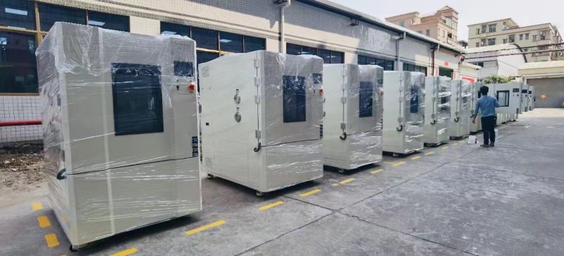
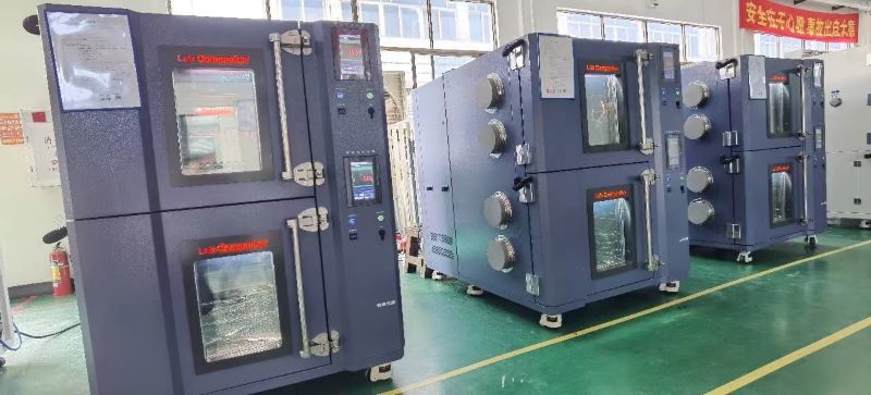
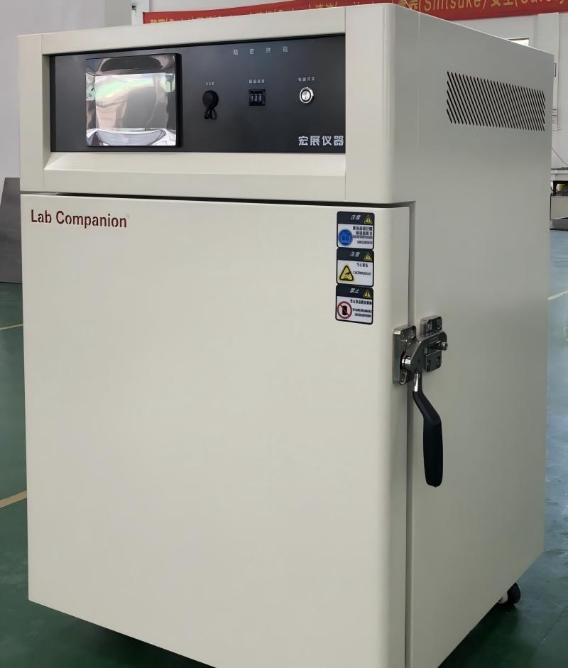
Hello, our company is a high-quality development team with strong technical strength, providing high-quality products, complete solutions, and excellent technical services to our customers. The main products include walk-in constant temperature and humidity testing chambers, UV accelerated aging testing machines, rapid temperature change testing chambers, walk-in environmental testing chambers, UV aging testers, constant temperature and humidity chambers, etc. Our company adheres to the principle of building a business with integrity, maintaining quality, and striving for progress. With a more determined pace, we continuously climb new heights and contribute to the national automation industry. We welcome new and old customers to confidently choose the products they like. We will serve you wholeheartedly!
A Tablet Computer, also known as a Tablet Personal Computer (Tablet PC), is a small, portable personal computer that uses a touch screen as its basic input device. It is an electronic product with strong mobility, and it can be seen everywhere in life (such as waiting stations, trains, high-speed trains, cafes, restaurants, meeting rooms, suburbs, etc.). People carry only simple coat protection or even no, in order to facilitate use, the design reduces the size, so that it can be directly placed in the pocket or handbag, backpack, but the tablet computer in the process of moving will also experience many environmental physical changes (such as temperature, humidity, vibration, impact, extrusion, etc.). Etc.) and natural damage (such as ultraviolet light, sunlight, dust, salt spray, water droplets... It will also cause artificial unintentional injury or abnormal operation and misoperation, and even cause failure and damage (such as: household chemicals, hand sweating, falling, terminal insertion and removal too much, pocket friction, crystal nails... These will shorten the life of the tablet computer, in order to ensure the reliability of the product and extend the service life to improve, we must carry out a number of environmental reliability test projects on the tablet computer, the following relevant tests for your reference.
Environmental test project description:
Simulate various harsh environments and reliability assessments used by tablet computers to test whether their performance meets the requirements; It mainly includes high and low temperature operation and high and low temperature storage, temperature and condensation, temperature cycle and shock, wet and heat combination test, ultraviolet, sunlight, drip, dust, salt spray and other tests.
Operating temperature range: 0℃ ~ 35℃/5% ~ 95%RH
Storage temperature range: -10℃ ~ 50℃/10% ~ 90%RH
Operating low temperature test: -10℃/2h/ power operation
Operating high temperature test: 40℃/8h/ all running
Storage low temperature test: -20℃/96h/ shutdown
Storage high temperature test: 60℃/96h/ shutdown
High temperature test of vehicle storage: 85℃/96h/ shutdown
Temperature shock: -40℃(30min)←→80℃(30min)/10cycle
Wet heat test: 40℃/95%R.H./48h/ power standby
Hot and humid cycle test: 40℃/95%R.H./1h→ramp:1℃/min→-10℃/1h, 20cycles, power standby
Wet heat test: 40℃/95%R.H./48h/ power standby
Hot and humid cycle test: 40℃/95%R.H./1h→ramp:1℃/min→-10℃/1h, 20cycles, power standby
Weather resistance test:
Simulation of the most severe natural conditions, solar thermal effect test, each cycle of 24 hours, 8 hours of continuous exposure, 16 hours to keep dark, each cycle radiation amount of 8.96 kWh/m2, a total of 10cycles.
Salt spray test:
5% sodium chloride solution/Water temperature 35°C/PH 6.5~7.2/24h/ Shutdown → Pure water wipe shell →55°C/0.5h→ Function test: after 2 hours, after 40/80%R.H./168h.
Dripping test: According to IEC60529, in line with IPX2 waterproof rating, can prevent water droplets falling at an Angle of less than 15 degrees from entering the tablet computer and causing damage. Test conditions: water flow rate 3mm/min, 2.5min at each position, checkpoint: after test, 24 hours later, standby for 1 week.
Dust Test:
According to IEC60529, in line with the IP5X dust class, can not completely prevent the entry of dust but does not affect the device should be the action and anquan, in addition to tablet computers are currently many personal mobile portable 3C products commonly used dust standards, such as: mobile phones, digital cameras, MP3, MP4... Let's wait.
Conditions:
Dust sample 110mm/3 ~ 8h/ test for dynamic operation
After the test, a microscope is used to detect whether dust particles will enter the interior space of the tablet.
Chemical staining test:
Confirm the external components related to the tablet, confirm the chemical resistance of household chemicals, chemicals: sunscreen, lipstick, hand cream, mosquito repellent, cooking oil (salad oil, sunflower oil, olive oil... Etc.), the test time is 24 hours, check the color, gloss, surface smoothness... Etc., and confirm whether there are bubbles or cracks.
Mechanical test:
Test the strength of the mechanical structure of the tablet computer and the wear resistance of the key components; Mainly includes vibration test, drop test, impact test, plug test, and wear test... Etc.
Fall test: The height of 130cm, free fall on the smooth soil surface, each side fell 7 times, 2 sides a total of 14 times, tablet computer in standby state, each fall, the function of the test product is checked.
Repeated drop test: the height of 30cm, free drop on the smooth dense surface of 2cm thickness, each side fell 100 times, each interval of 2s, 7 sides a total of 700 times, every 20 times, check the function of the experimental product, tablet computer is in the state of power.
Random vibration test: frequency 30 ~ 100Hz, 2G, axial: three axial. Time: 1 hour in each direction, for a total of three hours, the tablet is in standby mode.
Screen impact resistance test: 11φ/5.5g copper ball fell on the center surface of 1m object at 1.8m height and 3ψ/9g stainless steel ball fell at 30cm height
Screen writing durability: more than 100,000 words (width R0.8mm, pressure 250g)
Screen touch durability: 1 million, 10 million, 160 million, 200 million times or more (width R8mm, hardness 60°, pressure 250g, 2 times per second)
Screen flat press test: the diameter of the rubber block is 8mm, the pressure speed is 1.2mm/min, the vertical direction is 5kg force flat press the window 3 times, each time for 5 seconds, the screen should display normally.
Screen front flat press test: The entire contact area, the direction of the vertical 25kg force front flat press each side of the tablet computer, for 10 seconds, flat press 3 times, there should be no abnormal.
Earphone plug and remove test: Insert the earphone vertically into the earphone hole, and then pull it out vertically. Repeat this for more than 5000 times
I/O plug and pull test: The tablet is in standby state, and the plug terminal connector is pulled out, a total of more than 5000 times
Pocket friction test: Simulate various materials pocket or backpack, the tablet is repeatedly rubbed in the pocket 2,000 times (friction test will also add some mixed dust particles, including dust particles, yan grass particles, fluff and paper particles for mixing test).
Screen hardness test: hardness greater than class 7 (ASTM D 3363, JIS 5400)
Screen impact test: hit the most vulnerable sides and center of the panel with a force of more than 5㎏
1. Water absorbed by IC chip and lead frame and silver paste used in SMT
2. Moisture absorbed in the plastic sealing material
3. The device may be affected when the humidity in the plastic sealing room is high;
4. After the encapsulation of the device, water vapor permeates through the plastic sealant and the gap between the plastic sealant and the lead frame, because there is only a mechanical combination between the plastic and the lead frame, so there is inevitably a small gap between the lead frame and the plastic.
Note: As long as the gap between the sealant is greater than 3.4*10^-10m, water molecules can pass through the sealant protection Note: The airtight package is not sensitive to water vapor, generally do not use accelerated temperature and humidity test to evaluate its reliability, but to measure its air tightness, internal water vapor content, etc.
PCT test description for JESD22-A102:
It is used to evaluate the integrity of non-airtight packaged devices against water vapor in water vapor condensation or saturated water vapor environments. The sample is placed in a condensed, high-humidity environment under high pressure to allow water vapor to enter the package, exposing weaknesses in the package such as corrosion of the delamination and metallization layers. This test is used to evaluate new package structures or updates of materials and designs in the package body. It should be noted that there will be some internal or external failure mechanisms in this test that do not match the actual application situation. Since absorbed water vapor reduces the glass transition temperature of most polymer materials, an unreal failure mode may occur when the temperature is higher than the glass transition temperature.
External pin tin short circuit: The ionization effect caused by moisture in the package external pin will cause abnormal growth of ion migration, resulting in short circuit between pins.
Moisture causes corrosion inside the package:
The cracks caused by the moisture through the packaging process bring external ion contamination to the surface of the wafer, and after passing through the surface defects such as: protective layer pinholes, cracks, poor covers... Etc., into the semiconductor original, causing corrosion and leakage current... Such problems, if there is applied bias then the fault is more likely to occur.
PCT test conditions:
(Collate PCB, PCT, IC semiconductor and related materials have relevant test conditions on PCT[steam pot test]) PCT test purpose and application
Test name
temperature
humidity
time
Check items & add notes
JEDEC-22-A102
121 ℃
100%R.H.
168h
Other test time: 24h, 48h, 96h, 168h, 240h, 336h
Tensile stripping strength test of IPC-FC-241B-PCB copper laminated laminates
121 ℃
100%R.H.
100 h
The strength of the copper layer should be 1000 N/m
IC-Auto Clave test
121 ℃
100%R.H.
288h
Low dielectric high heat resistant multilayer board
121 ℃
100%R.H.
192h
PCB plug agent
121 ℃
100%R.H.
192h
PCB-PCT test
121 ℃
100%R.H.
30min
Check: Layers, bubbles, white spots
Lead-free solder accelerated life 1
100 ℃
100%R.H.
8h
Equivalent to 6 months under high temperature and humidity, activation energy =4.44eV
Lead-free solder accelerated life 2
100 ℃
100%R.H.
16h
Equivalent to a year of high temperature and humidity, activation energy =4.44eV
IC lead-free test
121 ℃
100%R.H.
1000h
Check every 500 hours
Liquid crystal panel adhesion test
121 ℃
100%R.H.
12h
Metal gasket
121 ℃
100%R.H.
24h
Semiconductor package test
121 ℃
100%R.H.
500, 1000 hours
PCB moisture absorption test
121 ℃
100%R.H.
5, 8h
FPC moisture absorption test
121 ℃
100%R.H.
192h
PCB plug agent
121 ℃
100%R.H.
192h
Multilayer material with low dielectric power and high heat resistance
121 ℃
100%R.H.
5h
Water absorption is less than 0.4 ~ 0.6%
High TG glass epoxy multilayer printed circuit board material
121 ℃
100%R.H.
5h
Water absorption is less than 0.55 ~ 0.65%
High TG glass epoxy multilayer printed circuit board - Heat resistance test after hygroscopic reflow welding
121 ℃
100%R.H.
3h
Heat resistance test of reflow welding after PCT test is completed (260℃/30 seconds)
Micro-etching Horizontal Browning (Co-Bra Bond)
121 ℃
100%R.H.
168h
Automotive PCB
121 ℃
100%R.H.
50, 100h
PCB for the main board
121 ℃
100%R.H.
30min
GBA carrier board
121 ℃
100%R.H.
24h
Accelerated wet resistance test of semiconductor devices
Cutting angles on a lathe is a very important activity in machining, regardless of the components' complexity or whether the fittings are custom made. The CNC machines (Computer Numerical Control) in modern manufacturing have changed the cutting angles process to a great extent by providing precise and efficient solutions that are much better than the traditional methods.
In this article, we are going to explain the cutting angles on a lathe using CNC technology, talk about the different tools and attachments used, and at last present the CNC products that serve this function.
Understanding CNC Lathes and Angle Cutting
Angling cuts on a lathe requires understanding first and foremost the working of CNC machines. CNC lathes follow the commands that you have recorded and are very precise when it comes to cutting complex angles because the computer controls the movement of cutting tools.
Why Use CNC for Cutting Angles on a Lathe?
A numerically controlled (CNC) machine is superior to human operators in achieving both precision and efficiency in cutting the pieces at a lathe. Contrarily to manual ways presented by human inconsistency, these machines aid in doing highly exact work by observing preset operating codes down to the smallest particulars. Preciseness is a prime demand in sectors such as aviation, automotive, and production, at which point a little error may destabilize the functionality of components.
CNC technology, on the other hand, is the other aspect of the main advantage - repetition. When the machine is programmed, it can create the same parts with very small non-standard characteristics of which the equipment is suited to mass production. On the other hand, manual cutting typically has operator errors that lead to small deviations in the parts.
Besides that,CNC lathes help save on time and manual labor, especially when they have to work on complex shapes or be able to keep up with the smallest deadlines. They are the most apt when it comes to precision, constancy, and rapidity, thus being the go-to technologies for manufacturing operations related to the cutting of angles.
Types of Angle Cutting on a Lathe
The lathe can operate with very high precision while cutting angles at different points along the workpiece perimeter. Here are the types that are most frequently seen by professionals:
External Angles
The CNC lathe is a CNC machine tool that can be used for machining different parts that have angled surfaces on the job. Sections of these mills can be easily programmed to form smooth transitions of depth by simply writing programs and, then, are directly cut along with the sharp tapers at the external surfaces. This practice is also helpful in purpose of finishing the conical blanks, as well. Conical blunt edges form very quickly for welding purposes are another advantage. The machine's high accuracy, in this form, will lead to a finish that is both very smooth and beautiful, especially when it comes to creating custom parts from fitting materials or mechanical parts, or just for visual variations.
Internal Angles
A hole where the interior is being worked on or a borehole is the most common place to cut internal angles. These cuts are important for applications such as the tapered threads or the internal tapers which in fact demand them for precision to fit together.
CNC lathes are the most efficient machines for internal angles where tight tolerances are required, even in deep bores, thus resulting in the seamless introduction of parts. Our drilling tool CNC machines are mainly used to improve productivity when we are working on limited angle spaces, as well as to make clean cuts in hard metals.
Chamfers
Chamfers are, basically, the extra beveled singes before the ends of a workpiece that give durability and a better look in general. These cuts, which can be in a few different degrees to be cut, are also used to get rid of sharp edges that possibly could hurt or damage.
Chamfers might be widespread and be present in various sizes and seat angles, and with the help of our CNC lathes, you can indeed adjust this cut to better suit the project's needs.
Main Geometric Angles and Selection of Lathe Tools
When it comes to a CNC lathe, the tool geometry is responsible for the cutting efficiency, precision, and surface finish. The following are the main angles of geometrical quantity and the theory of cutting tool selection based on them.
● Rake Angle: A rake angle is the angle between the workpiece and the cutting face of the tool. It is used to guide the chips away from the cutting spot. A positive rake angle diminishes the cutting force, minimizes heat. Thus, it means that the surface is smoother. However, for harder materials, a lower or zero rake should be advanced, so the tools last longer. Our carbide-tipped tools are developed with different rake angles, which allow for the most effective results in various materials.
● Clearance Angle: Whenever the tool moves, the backspace wipes out the rubbing on the tool, and the frictions decrease as well as the cutting efficiency improves. The frictionless cutting and long tool life depend on the right choice of the clearance angle. A higher clearance angle is advantageous in softer materials, while in harder materials a smaller pitch is needed for tool strength. We provide the precision cut turning and boring tool materials with the different clearance angles for different operations.
● Cutting Edge Angle: This angle of inclination directly affects chip formation and surface finish and thus directs the cutting force. In other words, a small cutting edge angle which yields a minimal load to the cutting forces may be associated with a short tool life on materials, particularly with very hard materials. The best option is the one that fits the material your machinist is working with and a specific surface finish.
Choosing the right tool with the geometric angles to carry out the cutting operation, you are also able to enhance cut conditions and gain dupe results in angle cutting for both external and internal angles.
Setting Up the CNC Lathe for Angle Cutting
The setup is the most important action to the cutting of angles on a lathe. Here, we provide step-by-step instructions as follows:
● Choosing the Right Tool: The chosen tool will be the one that best suits the material and the type of angle being cut. Our CNC-compatible tooling kits contain the complete set of a set of turning and boring tools that solve complex angles.
● Programming the CNC Lathe: It is done with the programming that the machine performs. Technicians can feed the G-code, which is either the exact angle and size or by using a user-friendly CAD/CAM interface. CNC machines are designed for both manual G-code programming and pre-programmed CAD designs, which makes the whole installation process very smooth.
● Workholding: Securing the material to machine the part is critical for a precise cut. For example, a project's needs may change, and we will work on the material differently using a collet, faceplate, or chuck. Our CNC lathes come complete with ultra-precision work holding systems to minimize workpiece movement during cutting.
Cutting Angles on a CNC Lathe: The Process
Once your CNC lathe has been set up, you can start the cutting process. It shows a step-by-step manual as follows:
1. Workpiece Loading: Make sure you fix the workpiece into the lathe's chuck or collet.
2. Initiate the Program: With the set programmed data, enable the cuts. The CNC system will automatically place the tool at the right angle, speed, and depth.
3. Perform the Cut: Although CNC machines make most of the work automatic, it's very important to watch the cutting process to be sure that the machine functions correctly. Our machines provide virtual real-time monitoring that lets operators make the necessary adjustments when the cut is in progress.
4. Complete Post-Processing: After the cut, a part might require some slight sanding or polishing, depending on what material it is made of. However, our CNC machines are built in a way that they minimize the post-processing by giving excellent surface finishes directly from the machine.
All our CNC lathe solutions have been designed optimally for both single-pass angle cutting and more complex multi-step processes, hence, you can be guaranteed of the best results each time.
Common Lathe CNC Cutting Tools for using on Angles
Cutting angles on a CNC lathe requires various specialized tools to ensure accuracy and efficiency. Below are some of the essential tools for this task:
● Turning Tools: Turning tools are primarily configured to cut external angles and to produce beveled surfaces. Shaping tools are necessary for both tapering or shaping the outside diameter of a workpiece. We have a large inventory of carbide-tipped turning tools, which are well known for their resistance to wear and tear as well as their high-speed performance precision. These tools guarantee smooth and precise cuts, which makes them the best option for external tapers or bevels.
● Boring Bars: For internal angles, boring bars are applied to reach inside a workpiece and cut tapers or angles. Our boring bars come in different dimensions and are suitable for heavy-duty applications where they can cut the hardest materials without any problem. They are optimal for the creation of internal tapers or bore angling with great precision, especially in hard-to-machine materials.
● Chamfering Tools: Chamfer tools come into play when making edges that have a bevel on a workpiece. Besides, such tools are the ones that are programmable to CNC lathes for chamfering edges automatically during the cutting cycle. Chamfering has the dual advantage of enhancing the visual appeal and strengthening the components, especially when the sharp edges have to be removed or softened.
What Is The Specific Effect Of The Lathe Tool Angle On The Cutting Force And Cutting Surface Quality?
The cutting tool's rake angle has a great effect on both the force and the surface finish quality of cutting action. Here are the ways in which different angles influence these outcomes:
● Cutting Force:The rake angle is the main factor influencing the cutting force intensity. A positive rake angle on the other hand, reduces the force by the provision of the machine with thinner and consequently, more manageable chips. This way the operation becomes smoother, wear on the tool is less, and it consumes less power. Meanwhile, a negative slope amplifies the cutting force, which is the cut & squats effect on tougher materials but which also creates more heat and stresses the cutting tool. By choosing the proper rake angle according to the hardness of the material, the best machining may be obtained with less force required.
● Surface Quality: The geometry of the tool also has a direct influence on the quality of the surface of the workpiece. A tool with a large rake angle generally yields a more polished surface because of the fact that it produces smaller chips and therefore less friction while it is cutting. Conversely, tools having small rake angles or high cutting edge angles might scratch the surface due to more chip resistance and cutting force. The clearance angle, in addition, keeps the same tool clear from actually contacting the surface. This would cause a finish that lacks durability.
Common Malfunctions when Angle Cutting: Diagnosis and Fix
Though CNC lathes are problematic, they are nevertheless very efficient and accurate for angle cutting. Here are some problems you need to know when you are working with CNC lathes :
● Tool Wear: It will create an inaccuracy to cut when the cutter is blunt. On the opposite side of the spectrum, our CNC machines have incorporated tool monitoring systems that fairly promptly alert the operator when something is wrong.
● Inaccurate Angle Cuts: This is either due to mistakes in the program or the movement of the equipment while cutting the material. The CNC system we use has invented precision calibration functions enabling it to be a whole entity with the specific program that is telling it to give the angle you want.
● Surface Finish: In case of a rough surface on angle it can be partly due to very high travel velocities and very low tool settings. Done by carefully adjusting the travel and feed rates the CNC lathe is used to mold smooth and final surfaces.
Optimizing Angle Cutting: Best Practices
A CNC lathe is a versatile tool for cutting angles, and although it requires the correct tools, it also needs the right approach to make the process precise, efficient, and of a high standard. Here are some best practices to help optimize your angle-cutting operations:
● Use the Correct Tools: Selecting the appropriate cutting tool is the main step for achieving precise angles as well as being clean. For external angles, the use of turning tools that are of high quality is recommended, while for internal angles boring bars that are suited both for the material and the type of cut should be used. Chamfering tools are the tools for the beveled edges. Every tool is made for specific tasks, so be sure to pair the right tool with the material and the angle specifications. The toolkits we have that are CNC-compatible include a vast collection of carbide-tipped turning tools, boring bars, and chamfering tools, all optimized for angle cutting.
● Fine-Tune CNC Programming: Correct programming is the key to the accurate cutting of the angles. Make sure that G-codes are precisely entered to define the angle, feed rate, speed, and depth of the cut. Slight mistakes in the programming can make the machine cut the wrong way, thus, spending much time and material. Our CNC machines are supplied with state-of-the-art programming interfaces which make it easy to set the correct parameters, and thus you get the precise angle you need.
● Maintain Proper Workholding: Proper workholding is the key to regularly maintaining the cutting operation's precise quality of a workpiece. Whether you're using a chuck, collet, or faceplate, ensure that the workpiece is firmly held to prevent any movement during operation. The workpiece can be any object in the vicinity and the workplace can be a shifted one that is inclined or tilted causing inaccurate angles and surface finish problems.
● Monitor Tool Wear: Monitor the wear of tools by inspecting them frequently. Cutting tools that are not sharp enough or are damaged can be responsible for poor cutting quality, roughness of the surface, and incorrect positioning. To guarantee smooth processing, our CNC machines are equipped with tool wear monitoring systems that warn operators when it's time to replace the tools.
By implementing these best practices, you can make the CNC angle-cutting process more efficient, waste-free, and have more precision.
Conclusion
In conclusion, The implementation of CNC technology in lathe work for cutting angles is now more than ever more accurate, efficient, and consistent. By utilizing our proven CNC lathes and toolkits, machinists can perform precise angle cuts on any material ranging from soft plastic to hardened metals. If you are a novice in CNC machining or want to upgrade your existing setup, our CNC products are suitable for angle-cutting tasks.
The integration of technology in our daily lives has reached new heights, and our kitchens are no exception. The emergence of smart kitchen displays has transformed the way we cook and prepare meals at home. This innovative kitchen tool combines the functionalities of a kitchen display industrial control system with the convenience and versatility of an Android all-in-one touch screen monitor computer.
Gone are the days of flipping through recipe books or struggling to follow cooking instructions on a tiny smartphone screen. With a smart kitchen display, all the information you need is at your fingertips. The large and vibrant touch screen allows you to browse through a vast repository of recipes, complete with step-by-step instructions, photos, and even videos.
Imagine preparing a complex dish and having the ability to adjust cooking times, temperatures, and other variables directly from a single device. The kitchen display industrial control component of this system ensures precise control over your appliances, making cooking more manageable and efficient. From setting oven temperatures to managing multiple timers, this technology simplifies the cooking process and ensures optimal results every time.
But the smart kitchen display is not just a cooking assistant. It’s also a multimedia hub that can entertain and inform you while you’re in the kitchen. The built-in Android all-in-one computer allows you to stream your favorite cooking shows and videos, listen to music, or catch up on the latest news and weather updates - all while keeping your hands free to prepare your culinary masterpiece.
The touch screen monitor computer offers a user-friendly interface that is intuitive and easy to navigate. You can customize the display to show your preferred cooking apps, kitchen timers, and even incorporate smart home automation controls for lighting and temperature.
In addition, the sleek design of the smart kitchen display makes it a stylish and modern addition to any kitchen. Its slim profile and seamless integration with other kitchen appliances make it aesthetically pleasing and functional.
The smart kitchen display is not just a technological novelty; it is revolutionizing home cooking. With its combination of a kitchen display industrial control system, Android all-in-one computer, and touch screen monitor, it elevates cooking to a whole new level. Say goodbye to complicated recipe books and tedious cooking processes, and welcome the future of home cooking with open arms.
If you are a mineral sand sorting machine enthusiast, you know how important it is to have efficient and reliable equipment. One key tool in your arsenal should be a chute style silica sand color sorting equipment. This type of machine offers advanced technology and features that can greatly enhance your sorting process. In this blog post, we will share some valuable tips and tricks to help you get the most out of your chute style sorting equipment.
1. Understand the Operating Principles
Before diving into sorting, it’s crucial to fully understand how the chute style silica sand color sorting equipment operates. Familiarize yourself with the machine’s specifications, settings, and controls. Take the time to read through the user manual and learn about its unique features and functionalities. This will lay a solid foundation for efficient and effective sorting.
2. Optimize Lighting Conditions
Proper lighting conditions are essential for accurate color sorting. Ensure that the sorting area is well-lit and free from glare or shadows that could interfere with the sorting process. Experiment with different light sources and angles to achieve the best results. Additionally, regular maintenance of the lighting system will help prevent any sudden discrepancies in color recognition.
3. Set Sorting Parameters
The chute style sorting equipment allows you to set specific parameters for sorting. Take advantage of this feature by defining the acceptable color range and variations that meet your quality standards. Adjust the sensitivity levels and sorting speeds according to the characteristics of the mineral sand you are sorting. Regularly fine-tune these parameters based on the feedback and results obtained.
4. Maintain a Clean Sorting Surface
A clean sorting surface is crucial for accurate color sorting. Regularly inspect and clean the equipment’s chute to remove any dust, debris, or residue that could affect the sorting process. Use appropriate cleaning materials and follow the manufacturer’s guidelines to ensure the longevity of the equipment and preserve the sorting accuracy.
5. Implement Regular Calibrations
Periodic calibration of your chute style silica sand color sorting equipment is vital for maintaining its accuracy and efficiency. Follow the manufacturer’s recommended calibration procedures and schedule routine checks to ensure optimal performance. Calibration helps align the machine’s sensors and settings, enhancing the accuracy of color recognition and sorting.
6. Safety Measures
While working with any machinery, safety should be a top priority. Ensure that all safety features are in place and functioning properly. Train your team on the correct operation and handling of the equipment to prevent accidents and injuries. Regularly inspect the equipment for any potential hazards and address them promptly.
7. Continuous Learning and Improvement
Stay updated with the latest advancements in chute style silica sand color sorting equipment. Attend industry conferences, webinars, or workshops to gain insights from experts and fellow enthusiasts. Network with other professionals in the field to exchange knowledge and experiences. Embrace continuous learning and improvement to stay ahead of the game.
By following these tips and tricks, you can effectively utilize chute style silica sand color sorting equipment for your mineral sand sorting needs. Remember to understand the operating principles, optimize lighting conditions, set sorting parameters, maintain a clean sorting surface, implement regular calibrations, prioritize safety, and pursue continuous learning for optimal results. Happy sorting!
High-density polyethylene (HDPE) is a widely used and recyclable plastic. Nonetheless, the presence of polypropylene (PP) contamination poses a significant issue in recycled HDPE streams.
Plastic Mixture
Can PP and HDPE be recycled together? PP and HDPE are distinct types of plastic with different chemical compositions and properties. When they are mixed together in the recycling stream, it can result in various issues:
Reduced quality: Mixing PP with HDPE can lead to lower-quality recycled HDPE material. The properties of the resulting plastic may not meet the required standards for certain applications.
Compatibility issues: PP and HDPE have different melting points and processing requirements. Combining them can make it difficult to maintain the consistency and quality of the recycled material during the melting and molding stages.
Material weakness: The combination of PP and HDPE can result in a recycled material that has reduced strength, durability, and performance. This can be problematic, especially in applications where HDPE's mechanical properties are critical.
Identification and Separation of polymers in the industry One of the biggest challenges facing the plastics recycling industry today is separating all of the various polymers entering the recycling stream. Separating PP from HDPE during the recycling process can be challenging due to their similar appearance. This can result in contamination if they are not adequately separated at recycling facilities.
To mitigate contamination issues, recycling facilities often employ advanced sorting and separation technologies to ensure that PP and HDPE are properly separated. This involves using optical sorters, air classifiers, and other equipment to identify and separate different types of plastics.
Near Infrared (NIR) Sorting Technology
Among them, the NIR-based sorting machines are widely used in the recycling industry to identify and separate various types of plastics based on their unique spectral signatures in the near-infrared range. These machines can accurately differentiate between different polymer types, such as PET, HDPE, PP, PVC, and more, facilitating the efficient recycling of plastics and reducing contamination in the recycling stream.
PP & HDPE Flakes Separation
AMD's plastic color sorting machines are known for the high accuracy and reliability. We contribute to efficient recycling operations by reducing contamination in the recycling stream and ensuring the production of clean, high-quality recycled materials.
The macadamia industry is growing amid a rapidly changing world. What worked yesterday might not work tomrrow. Delivering a high quality product to broad base of comsumers is imperative to maintaning prices. And continuous growth in consumption requires continuous innovation.
With leading multi-spectral detection technology, AMD® sorters provide superior detection capabilities to help you eliminate defects in macadamia nuts and ensure consistent food safety.
AMD has introduced a comprehensive inspection and sorting solution for the macadamia nut industry. This solution is applicable to both external and internal inspection of inshell macadamia nuts, as well as color and shape sorting of macadamia kernels, among other functions, assisting enterprises in enhancing both the yield and quality of their products.
INSHELL MACADAMIA NUTS SORTING
External Sorting
AMD® LGY Series Belt-type Optical Sorting Machine can replace manual work and accurately identify the defects of shelled macadamia nuts including obvious breakage, abnormal colour spots, dirty nuts, mold filaments and other substandard products.
Based on visible light technology, the AMD® LGY offers processors the flexibility of sorting different varieties and grades of macadamia nuts in-shell, whole, halves, and pieces.
AMD® LGY Inshell Macadamia Nuts Color Sorting Machine
Internal Sorting The AMD® KXA6 Series X-ray inspection system can effectively remove the typical internal defects of macadamia nut-in-shell, such as empty, shriveled, discolored, cracked shell, rotten, insect-damaged nuts caused by stink bugs. Tailored algorithm for macadamia nuts, featuring large yield, high precision, low carry-out, low radiation value.
AMD® KXA6 Series X-ray Inspection System for Inshell Macadamia Nuts
Macadamia Nut Kernel Sorting
Based on AI deep learning, visible light and infrared sorting technology, AMD® P-LGID series sorting equipment can achieve kernel-shell separation while accurately identifying and separating different colours, and rejecting defective products such as insect damage, shrivelled, mouldy and dried.
AMD® P-LGID4 AI Sorting Machine for Macadamia Nut Kernel
Safeguarding food safety in nut processing. Boost efficiency, reduce waste, and minimize labor reliance. AMD® COLOR SORTER take macadamia nuts grading to new levels.
Get in touch with one of our sales manager today and get tailored macadamia nuts sorting machines & solution.
Boating enthusiasts know that maintaining a clean and well-kept vessel is crucial for ensuring its longevity and functionality. Whether you're navigating through salty waters, fishing, or simply cruising, your boat inevitably collects grime, fish scales, salt deposits, and other debris. One of the best ways to keep your boat in tip-top shape is by using a washdown pump. This blog will explore everything you need to know about washdown pumps for boats, from their benefits to installation and maintenance tips.
What is a Washdown Pumpfor Boats?
A washdown pump is a high-pressure water pump designed to quickly and efficiently clean a boat’s deck, hull, anchor, and other areas. By spraying pressurized water, it helps remove stubborn dirt, salt, and fish residue that can accumulate during a day out on the water. These pumps typically pull water from a seawater intake or a freshwater tank onboard and deliver it through a hose and spray nozzle for easy, targeted cleaning.
Why Do You Need a Washdown Pump?
Boats are constantly exposed to elements that can wear them down over time. Without regular cleaning, salt buildup, algae, fish guts, mud, and other debris can lead to corrosion, unpleasant smells, and even safety hazards due to slippery decks. Here’s why a washdown pump is essential:
Efficient Cleaning: The high pressure from a 51 series deck marine washdown pump makes quick work of tough grime and fish residue that a standard hose might not be able to remove.
Time-Saving: Cleaning your boat with a bucket or low-pressure hose can be time-consuming and less effective. A washdown pump allows you to clean large areas in a fraction of the time.
Conserves Water: By using pressurized water, these pumps make the cleaning process more efficient and often reduce the amount of water required to achieve a thorough clean.
Keeps Your Boat Looking Great: A clean boat not only performs better but also looks better. Regular use of a washdown pump helps maintain the aesthetic appeal of your boat, keeping it in pristine condition.
Freshwater Washdown Pumps: These pumps draw water from an onboard freshwater tank. They are more commonly used on smaller vessels or when seawater is unavailable. Freshwater is particularly useful for rinsing off salt deposits at the end of the day to prevent corrosion.
Key Features to Look for in a Washdown Pump
When selecting a marine deck washdown pump for your boat, consider the following features to ensure you get the best one for your needs:
Flow Rate (GPM): The pump’s flow rate, measured in gallons per minute (GPM), determines how much water is being delivered. A higher GPM means a stronger and faster cleaning process. Typically, boats need pumps that deliver between 3 and 5 GPM.
Water Pressure (PSI): A higher PSI (pounds per square inch) indicates stronger water pressure, which is crucial for removing tough grime. Look for a pump that provides at least 60 PSI, with higher-end models reaching up to 70-80 PSI for more demanding cleaning tasks.
Self-Priming: A self-priming pump can lift water from below the pump’s level, meaning you won’t have to manually prime it each time. This is a handy feature, especially when the pump is drawing from a seawater intake.
Thermal Overload Protection: Look for pumps with built-in protection against overheating. This ensures your pump won’t be damaged from overuse or extended periods of operation.
Ease of Installation: Some pumps come with pre-assembled kits, making them easier to install without professional help. Ensure the pump you select is compatible with your boat's system and easy to install.