头部背景图片

CNC Machining Design Guide

2024-11-21

Introduction to CNC Machining

Computer Numerical Control (CNC) machining is a manufacturing process that employs computerized controls and machine tools to remove layers of material from a workpiece, producing custom-designed parts. This technology is essential for manufacturing high-precision and complex components across various industries. CNC machining offers advantages such as high precision, repeatability, and the ability to produce complex geometries.

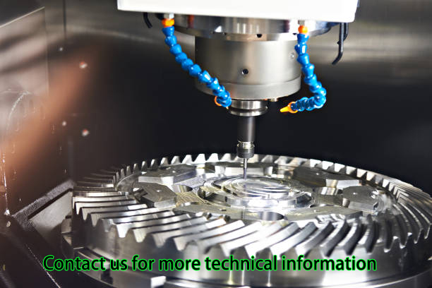
CNC machines operate through pre-programmed software and code that controls the movement of production equipment. This automation allows for the high-precision creation of parts and components that meet exacting specifications. The primary types of CNC machines include mills, lathes, and routers, each suitable for different types of machining tasks.


Key Products Offered

At CNC Yangsen, we specialize in the production of high-quality CNC machined parts. Our product range includes:

· CNC Machined Aluminum Parts: Lightweight, durable, and corrosion-resistant parts used in aerospace, automotive, and electronics.

· CNC Machined Steel Parts: Strong and wear-resistant components ideal for heavy machinery and industrial applications.

· CNC Machined Plastic Parts: Lightweight and versatile parts used in medical devices, consumer electronics, and automotive interiors.

· CNC Prototyping Services: Rapid production of prototypes to test designs before mass production.


CNC Machined Aluminum Parts

Aluminum is a popular material in CNC machining due to its excellent machinability, strength-to-weight ratio, and resistance to corrosion. CNC machined aluminum parts are commonly used in industries such as aerospace, automotive, and electronics. At CNC Yangsen, we produce a wide range of aluminum parts, including housings, brackets, and heat sinks.

CNC Machined Steel Parts

Steel offers superior strength and durability, making it ideal for heavy-duty applications. Our CNC machined steel parts are used in industries like construction, industrial machinery, and transportation. We provide various steel components, such as gears, shafts, and structural supports, ensuring they meet the highest quality standards.

CNC Machined Plastic Parts

Plastic materials are favored for their versatility, light weight, and cost-effectiveness. CNC machined plastic parts are utilized in medical devices, consumer electronics, and automotive interiors. CNC Yangsen manufactures plastic components with precision, catering to intricate designs and specific functional requirements.

CNC Prototyping Services

Prototyping is a critical step in product development, allowing for design validation and functional testing. Our CNC prototyping services enable rapid production of prototypes, helping clients refine their designs before committing to mass production. This process reduces time-to-market and ensures the final product meets all specifications.

Benefits of CNC Machining

High Precision and Accuracy

CNC machining offers unparalleled precision, with tolerances often within ±0.001 inches. This accuracy is crucial for industries requiring tight tolerances, such as aerospace and medical devices. The high precision of CNC machining results from its automated control, reducing human error and ensuring consistent quality across production runs.

Consistency and Repeatability

Once a design is programmed into a CNC machine, it can produce identical parts with consistent quality. This repeatability is essential for large production runs and maintaining product standards. CNC machines can operate continuously, producing parts that match the original design specifications without variation.

Complex Geometries

CNC machines can produce complex shapes and intricate designs that would be difficult or impossible to achieve with manual machining. This capability opens up new possibilities in product design and engineering. Features such as internal cavities, intricate surface details, and complex curves are achievable with CNC machining.

Material Versatility

CNC machining is compatible with a wide range of materials, including metals, plastics, and composites. This versatility allows manufacturers to select the best material for their specific application. Whether the need is for high-strength metal parts or lightweight plastic components, CNC machining can accommodate diverse material requirements.

Cost-Effective Production

While the initial setup costs for CNC machining can be high, the process becomes cost-effective for large production runs. The automation of the machining process reduces labor costs and increases production speed. Additionally, CNC machining minimizes material waste, contributing to overall cost savings.


Design Considerations for CNC Machining

Material Selection

Choosing the right material is crucial for the success of your CNC machining project. Consider factors such as material strength, weight, machinability, and cost. Common materials include aluminum, steel, titanium, and various plastics. The choice of material impacts the part's performance, durability, and cost.

Tolerances

Define the tolerances required for your parts. Tighter tolerances increase machining time and cost, so it's essential to balance precision with budget constraints. Understanding the functional requirements of the part helps in setting appropriate tolerances, ensuring it performs as intended without unnecessary machining expenses.

Surface Finish

The surface finish of CNC machined parts can vary from rough to highly polished, depending on the application. Specify the desired surface finish to ensure the final product meets your requirements. Factors such as the material, machining process, and post-processing steps influence the achievable surface finish.

Feature Design

Design features such as holes, threads, and pockets with manufacturability in mind. Avoid deep cavities, thin walls, and complex internal geometries that can be challenging to machine. Simplifying complex features where possible can reduce machining time and costs, while still achieving the desired functionality.

Tooling and Fixtures

Consider the tooling and fixtures needed to hold and machine your parts. Proper fixturing ensures stability and accuracy during machining. Designing parts that are easy to fixture can reduce setup times and improve overall machining efficiency. Collaboration with the machining team during the design phase can optimize the use of tooling and fixtures.


CNC Machining Process Overview

Designing the CAD Model

The first step in CNC machining is designing the part using Computer-Aided Design (CAD) software. This digital model serves as the blueprint for the machining process. The CAD model contains all the geometric information required to produce the part, including dimensions, tolerances, and surface finishes.

Converting CAD to CAM

The CAD model is then converted into a Computer-Aided Manufacturing (CAM) program. CAM software generates the toolpaths and G-code that control the CNC machine. The toolpaths determine the movement of the cutting tool, while the G-code provides specific instructions for machine operations such as speed, feed rate, and tool changes.

Setting Up the CNC Machine

Operators set up the CNC machine by installing the necessary tooling and fixtures. They also load the CAM program into the machine's controller. Proper setup ensures the machine operates correctly and produces parts to the required specifications. This step includes calibrating the machine, securing the workpiece, and verifying the toolpaths.

Machining the Part

The CNC machine follows the programmed toolpaths to remove material and shape the part. This process can involve multiple steps, such as roughing, finishing, and drilling. Roughing removes the bulk of the material quickly, while finishing achieves the final dimensions and surface finish. Drilling and other secondary operations are performed as needed.

Quality Control

After machining, the part undergoes quality control checks to ensure it meets the specified tolerances and dimensions. Inspection techniques include coordinate measuring machines (CMMs) and optical scanners. Quality control ensures that each part conforms to the design specifications and functions as intended.


Comparison of Common CNC Machining Materials

Material

Properties

Applications

Aluminum

Lightweight, corrosion-resistant

Aerospace, automotive, electronics

Steel

Strong, wear-resistant

Heavy machinery, industrial parts

Titanium

High strength-to-weight ratio

Aerospace, medical implants

Plastic

Lightweight, versatile

Medical devices, consumer products


Advanced CNC Machining Techniques

5-Axis CNC Machining


5-axis CNC machining allows for the movement of the cutting tool along five different axes simultaneously. This capability enables the production of highly complex and precise parts, reducing the need for multiple setups and increasing efficiency. It is particularly beneficial for aerospace and automotive components, where intricate designs and tight tolerances are required.

Multi-Spindle CNC Machining

Multi-spindle CNC machines have multiple spindles operating simultaneously, allowing for the machining of several parts at once. This technique significantly boosts productivity and is ideal for high-volume production runs. By machining multiple parts simultaneously, multi-spindle machines reduce cycle times and increase throughput.

Swiss-Style CNC Machining

Swiss-style CNC machines are designed for machining small, intricate parts with high precision. These machines are commonly used in the production of medical devices, watch components, and electrical connectors. Swiss-style machining excels in producing long, slender parts and features requiring tight tolerances and fine finishes.

CNC Turning

CNC turning is a machining process where a cutting tool, typically a non-rotary tool bit, moves linearly while the workpiece rotates. This technique is used to create cylindrical parts and is highly effective for producing parts with rotational symmetry. Common applications include shafts, bushings, and pulleys.

CNC Milling

CNC milling involves the movement of the cutting tool along multiple axes to remove material from the workpiece. This process is versatile and can produce a wide range of part geometries. CNC mills can perform operations such as drilling, tapping, and cutting slots, making them suitable for producing complex shapes and intricate features.


Post-Processing in CNC Machining

Deburring

Deburring removes sharp edges and burrs left from the machining process. This step improves the part's safety and functionality. Methods for deburring include manual processes, such as filing or sanding, and automated techniques, such as tumbling or vibratory finishing.

Anodizing

Anodizing is an electrochemical process that enhances the surface properties of aluminum parts, providing improved corrosion resistance and aesthetic appeal. The process involves immersing the part in an electrolyte bath and applying an electric current, resulting in a durable oxide layer.

Heat Treatment

Heat treatment alters the physical and mechanical properties of metal parts, enhancing their hardness, strength, and durability. Processes such as annealing, quenching, and tempering are used to achieve the desired material properties. Heat treatment is critical for parts subjected to high stress or demanding operational conditions.

Coating and Painting

Coating and painting protect CNC machined parts from corrosion and wear while improving their appearance. Various coatings, such as powder coating, electroplating, and painting, are available depending on the material and application requirements. Coatings can also provide additional properties, such as electrical insulation or enhanced wear resistance.


CNC Machining Applications

Aerospace Industry

The aerospace industry demands high-precision and high-performance parts, making CNC machining an ideal solution. Components such as engine parts, landing gear, and structural elements are often produced using CNC machining. The ability to machine complex geometries and maintain tight tolerances ensures the reliability and safety of aerospace components.

Automotive Industry

CNC machining is widely used in the automotive industry to produce parts such as engine components, transmission parts, and custom interior elements. The process ensures that parts meet stringent quality standards and performance criteria. CNC machining's versatility allows for the production of both prototype and production parts, supporting the entire product lifecycle.

Medical Industry

In the medical industry, CNC machining produces precision parts for devices such as implants, surgical instruments, and diagnostic equipment. The high precision and repeatability of CNC machining ensure that medical parts meet the required safety and performance standards. Materials such as titanium and high-grade plastics are commonly used for their biocompatibility and durability.

Electronics Industry

CNC machining creates components for consumer electronics, including housings, connectors, and heat sinks. The ability to machine intricate designs and maintain tight tolerances ensures that electronic parts fit and function correctly. CNC machining supports the rapid development and production of electronic devices, keeping pace with the industry's fast innovation cycle.

Industrial Machinery

CNC machining is crucial for manufacturing parts used in industrial machinery, such as gears, bearings, and tooling components. The durability and precision of CNC machined parts enhance the performance and longevity of industrial


CNC Machining Techniques and Their Applications

Technique

Description

Applications

5-Axis CNC Machining

Movement along five axes for complex parts

Aerospace, automotive components

Multi-Spindle CNC

Simultaneous machining with multiple spindles

High-volume production

Swiss-Style CNC

Precision machining of small, intricate parts

Medical devices, watch components

CNC Turning

Rotating workpiece with linear tool movement

Shafts, bushings, pulleys

CNC Milling

Multi-axis tool movement for complex geometries

Various parts, complex shapes


Choosing the Right CNC Machining Partner

Experience and Expertise

Select a CNC machining partner with extensive experience and expertise in the industry. Their knowledge and skills ensure that your parts are manufactured to the highest standards. Look for a partner with a proven track record and a diverse portfolio of successful projects.

Quality Control

Ensure that your CNC machining partner has stringent quality control processes in place. This includes using advanced inspection equipment and adhering to industry standards. A commitment to quality control guarantees that your parts meet all specifications and performance requirements.

Material Capabilities

Verify that your CNC machining partner can work with the materials required for your project. Their ability to handle a variety of materials, including metals, plastics, and composites, ensures that they can meet your specific needs. Material capabilities also indicate the partner's versatility and readiness to tackle diverse machining challenges.

Production Capacity

Consider the production capacity of your CNC machining partner. They should be able to handle both small and large production runs efficiently. Adequate production capacity ensures timely delivery of parts, whether you need a few prototypes or a high-volume production run.

Customer Support

Choose a CNC machining partner that provides excellent customer support. They should be responsive to your inquiries, offer technical assistance, and keep you informed throughout the machining process. Strong customer support fosters a collaborative relationship and ensures that your project progresses smoothly.


Conclusion

CNC machining is a versatile and powerful manufacturing process that offers numerous benefits, including high precision, consistency, and the ability to produce complex geometries. By understanding the key design considerations and advanced techniques, you can optimize your CNC machining projects for success. At CNC Yangsen, we are committed to providing top-quality CNC machined parts tailored to your specific needs.

Our expertise in CNC machining, combined with our dedication to customer satisfaction, makes us the ideal partner for your manufacturing needs. Whether you require precision aluminum parts, durable steel components, or intricate plastic parts, we have the capabilities to deliver. Contact us today to learn more about our products and services and how we can support your next project.

Burn-in Oven

2024-11-20

Burn-in Oven

Burn-in is an electrical stress test that employs voltage and temperature to accelerate the electrical  failure of a device.  Burn-in essentially simulates the operating life of the device, since the electrical excitation applied during burn-in may mirror the worst-case bias that the device will be subjected to in the course of its useable life.  Depending on the burn-in duration used,  the reliability information obtained  may pertain to the device's early life or its wear-out.  Burn-in may be used as a reliability monitor or as a production screen to weed out potential infant mortalities from the lot.

Burn-in is usually done at 125 deg C, with electrical excitation applied to the samples.  The burn-in process is facilitated by using burn-in boards (see Fig. 1) where the samples are loaded. These burn-in boards are then inserted into the burn-in oven (see Fig. 2), which supplies the necessary voltages to the samples while maintaining the oven temperature at 125 deg C.  The electrical bias applied may either be static or dynamic, depending on the failure mechanism being accelerated.

Figure 1.  Photo of Bare and Socket-populated Burn-in Boards

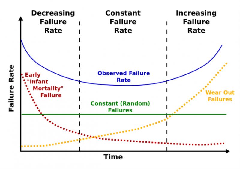
The operating life cycle distribution of a population of devices may be modeled as a bath tub curve, if the failures are plotted on the y-axis against the operating life in the x-axis.  The bath tub curve shows that the highest failure rates experienced by a population of devices occur during the early stage of the life cycle, or early life, and during the wear-out period of the life cycle.  Between the early life and wear-out stages is a long period wherein the devices fail very sparingly.   

Burn-in Oven

Figure 2.  Burn-in ovens

Early life failure (ELF) monitor burn-in, as the name implies,  is performed to screen out potential early life failures. It is conducted for a duration of 168 hours or less, and normally for only 48 hours.  Electrical failures after ELF monitor burn-in are known as early life failures or infant mortality, which means that these units will fail prematurely if they were used in their normal operation.

High Temperature Operating Life (HTOL) Test is the opposite of ELF monitor burn-in, testing the  reliability of the samples in their wear-out phase. HTOL is conducted for a duration of 1000 hours, with intermediate read points at 168 H and 500 H.  

Although the electrical excitation applied to the samples are often defined in terms of voltages, failure mechanisms accelerated by current (such as electromigration) and electric fields (such as dielectric rupture) are understandably accelerated by burn-in as well.  

Double 85 Constant Temperature And Humidity Reliability Environmental Test (THB)

2024-11-20

Double 85 Constant Temperature And Humidity Reliability Environmental Test (THB)

First, high temperature and humidity test

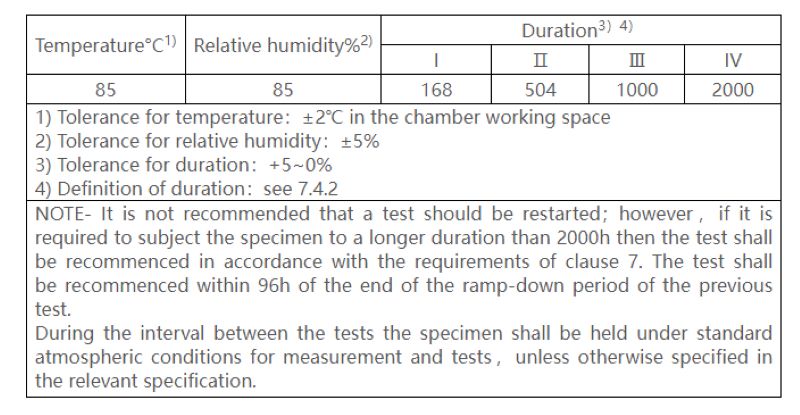
WHTOL (Wet High Temperature Operating Life) is a common environmental stress acceleration test, usually 85℃ and 85% relative humidity, which is generally carried out in accordance with the standard IEC 60068-2-67-2019. The test conditions are shown in the chart.

Second, the test principle

"Double 85 test" is one of the reliability environmental tests, mainly used for constant temperature and humidity box, that is, the temperature of the box is set to 85℃, the relative humidity is set to 85%RH conditions, to accelerate the aging of the test product. Although the test process is simple, the test is an important method to evaluate many characteristics of the test product, so it has become an indispensable reliability environmental test condition in various industries.

After aging the product under the condition of 85℃/85%RH, compare the performance changes of the product before and after aging, such as the photoelectric performance parameters of the lamp, the mechanical properties of the material, yellow index, etc., the smaller the difference, the better, so as to test the heat and moisture resistance of the product.

The product may have thermal failure when working in a continuous high temperature environment, and some moisture sensitive devices will fail in a high humidity environment. The dual 85 test can test the thermal stress generated by the product under high humidity and its ability to resist long-term moisture penetration. For example, the frequent failure of various products in the humid weather period in the south is mainly due to the poor temperature and humidity resistance of the products.

3. Experimental factors

In the LED lighting industry, many manufacturers have used the double 85 test results as an important means to judge the quality of lamps. Various possible reasons why LED lamps fail the dual 85 test are:

1. Lamp power supply: poor heat resistance of shell, danger of short circuit in circuit, failure of protection mechanism, etc.

2. Lamp structure: unreasonable design of heat dissipation body, installation problems, materials are not resistant to high temperature.

3. Lamp light source: poor moisture resistance, packaging adhesive aging, high temperature resistance.

If you encounter a special use environment, such as the working environment temperature is severe, you need to test its high and low temperature resistance, the test method can refer to the high and low temperature test project.

4. Serve customers

01. Customer group

LED lighting factory, LED power plant, LED packaging factory

02. Means of detection

Constant temperature and humidity test chamber

03. Reference standards

Constant temperature and humidity tests for electrical and electronic products -- Environmental testing -- Part 2: Test methods -- Test Cab: Constant temperature and humidity test GB/T 2423.3-2006.

04. Service content

4.1 Refer to the standard, conduct double 85 test on the product, and provide the third party's test results report.

4.2 Provide the analysis and improvement plan of the product through the double 85 test.

High Temperature And High Humidity Test Chamber

High Temperature Aging Cabinet

2024-11-20

High Temperature Aging Cabinet

High temperature aging cabinet is a type of aging equipment used to remove early failure of non-conforming product parts.

Use of temperature aging cabinet, aging oven:

This test equipment is a test equipment for aviation, automobile, home appliances, scientific research and other fields, which is used to test and determine the parameters and performance of electrical, electronic and other products and materials after temperature environment changes in high temperature, low temperature, alternating between temperature and humidity or constant temperature and humidity.

The chamber of the test equipment is sprayed with steel plate after treatment, and the spray color is optional, generally beige. SUS304 mirror stainless steel is used in the inner room, with a large window tempered glass, real-time observation of internal aging products.

Features of temperature aging cabinet, aging oven:

1. PLC processing industry touch screen programming combination control, balanced temperature control system: aging specimen room temperature rise start the ventilation fan, balance the sample heat, aging cabinet is divided into product area and load area

2. PID+SSR temperature control system: according to the temperature change in the specimen box, the heat of the heating tube is automatically adjusted to achieve the temperature balance, so that the heating heat of the system is equal to its heat loss and achieve the temperature balance control, so it can run stably for a long time; The fluctuation of temperature control is less than ±0.5℃

3. The air transport system is composed of three-phase asynchronous electronic multi-wing wind wheel and wind drum. The wind pressure is large, the wind speed is uniform, and the uniformity of each temperature point is met

4. High precision PT100 platinum resistance for temperature acquisition, high accuracy for temperature acquisition

5. Load control, the load control system provides ON/OFF control and timing control two functional options to meet the different test requirements of the product

(1)ON/OFF function introduction: The switch time, stop time, and cycle times can be set, the test product can be switched according to the setting requirements of the system, the stop cycle control, the aging cycle number reaches the set value, the system will automatically sound and light prompt

(2) Timing control function: the system can set the running time of the test product. When the load starts, the product power supply starts timing. When the actual timing time reaches the time set by the system, the power supply to the product is stopped

6. System operation safety and stability: The use of PLC industrial touch screen control system, stable operation, strong anti-interference, convenient program change, simple line. Perfect alarm protection device (see protection mode), real-time monitoring of the operating status of the system, with the function of automatic maintenance of temperature data during operation, in order to query the temperature historical data when the product is aging, the data can be copied to the computer through the USB interface for analysis (format is EXCEL), with historical data curve display function, It intuitively reflects the temperature change in the product area during the product test, and its curve can be copied to the computer in BMP format through the USB interface, so as to facilitate the operator to make the test product report. The system has the function of fault query, the system will automatically record the alarm situation, when the equipment fails, the software will automatically pop up the alarm screen to remind the cause of the fault and its solution; Stop the power supply to the test product to ensure the safety of the test product and the equipment itself, and record the fault situation and occurrence time for future maintenance.

High Temperature Aging Cabinet

High Temperature Furnace Inspection Index

2024-11-20

High Temperature Furnace Inspection Index

What is the high temperature furnace test standard? What metrics are tested? How long is the detection cycle? Which items are tested?

Test items (reference) :

Temperature uniformity test, system accuracy test, temperature, system accuracy, temperature uniformity, high temperature furnace verification and calibration, high temperature furnace (tube furnace) verification and calibration, box resistance furnace (high temperature furnace, heat treatment furnace) verification and calibration, high temperature furnace (box resistance furnace, dry furnace, heat treatment furnace) verification and calibration, silica

List of testing standards:

1, NCS/ CJ M61; SAE AMS 2750; JJF1376 High temperature furnace calibration specification NCS/ CJ M61, high temperature furnace calibration method SAE AMS 2750E, box type resistance furnace calibration specification JJF1376

2, AMS 2750F High temperature measurement AMS 2750F

3, GB 25576-2010 Food safety national standard Food additive silica (high temperature furnace method)

4, JJF 1184 thermocouple verification furnace temperature field test technical specification

5, AMS 2750E high temperature measurement AMS 2750E

6, AMS 2750F high temperature determination method 3.5

7, AMS 2750G high temperature measurement AMS 2750G

8, AMS 2750E high temperature determination method 1

9. JJF 1376; AMS 2750; JJG 276 Calibration specification for box type resistance furnace JJF 1376, high temperature measurement method AMS 2750E, high temperature creep, durable strength testing machine verification regulation JJG 276

10, JJF 1376 box type resistance furnace calibration specification

11, GB/T 9452-2012 heat treatment furnace effective heating zone determination method 1

12. SAE AMS 2750 high-temperature calibration method F

Lab Companion-Rapid Temperature Cycling Test Chamber

2024-11-20

Lab Companion-Rapid Temperature Cycling Test Chamber

Introduction of Lab Companion

With over 20 years of experience, Lab Companion is a world class manufacturer of environmental chambers and an accomplished supplier of turn-key test systems and equipment.  All our chambers build on Lab Companion’s reputation for long life and exceptional reliability.

 With a scope of design, manufacture and service, Lab Companion has established a quality management system that complies with the International Quality System Standard ISO 9001:2008.  Lab Companion’s equipment calibration program is accredited to the International Standard ISO 17025 and the American National Standard ANSI/NCSL-Z-540-1 by A2LA.  A2LA is a full member and signatory of the International Laboratory Accreditation Cooperation (ILAC), the Asia Pacific Laboratory Accreditation (APLAC) and the European Cooperation for Accreditation (EA). 

Lab Companion’s SE-Series Environmental Test Chambers offer a significantly enhanced airflow system, which provides better gradients and improved product temperature change rates.  These chambers utilize Thermotron’s flagship 8800 Programmer/Controller featuring a high resolution 12.1” flat panel display with touch screen user interface, expanded capabilities to graph, data log, edit, access on-screen help, and long term hard drive data storage.

Not only do we offer the highest quality products, we also provide ongoing support designed to keep you up and running long after the initial sale.  We provide factory direct local service with an extensive inventory of the parts you might need. 

Performance

Temperature range: -70°C to +180°C

Performance: With 23 Kg aluminum load (IEC60068-3-5), the rising rate from +85°C to -40°C is 15℃/min; the cooling rate from -40°C to +85°C is15℃/min too.

Temperature control:± 1°C Dry bulb temperatures from control point after stabilization at the control sensor

Performance is based on an ambient condition of 75°F (23.9°C) and 50% RH

Cooling/Heating Performance based on measurement at the control sensor in the supply air stream

Constructure

Interior

Nonmagnetic Series 300 stainless steel with a high nickel content

Internal seams heliarc welded for hermetic sealing of the liner

Corners and seams designed to allow for expansion and contraction under the temperature extremes encountered

Condensate drain located in the liner floor and under the conditioning plenum

Chamber base is fully welded

“Ultra-Lite” non-settling fiberglass insulation

One adjustable interior stainless steel shelf is standard

Exterior

Die-formed treated sheet steel

Metal access covers provided for easy opening doors to electrical components

Finish water-based, air dry lacquer, sprayed over a cleaned and primed surface

Easy lift-off hinged access doors for servicing the refrigeration system

One 12.5 cm diameter access port with interior weld and removable insulating plug mounted in right hand side wall accessories on hinged door for easy access

Features

Chamber Operation clearly displays helpful run-time information

Graphing Screen offers expanded capabilities, enhanced programming and reporting

System Status displays crucial refrigeration system parameters

Program Entry makes it easy to load, view and edit profiles

Set Up quick-step wizards make profile entry easy

Pop-up Refrigeration Charts for handy reference

Therm-Alarm® provides over & under temperature alarm protection

Activity Log Screen provides comprehensive equipment history

Web Server allows internet access to equipment via Ethernet

User-Friendly Pop-up Key Pad makes data entry quick and easy

Includes:

- Four USB Ports-two External & two Internal

- Ethernet

- RS-232

Technical specifications

1-4 independently programmable channels

Measuring Accuracy: 0.25% of span typical

Selectable °C or °F temperature scale

12.1” (30 cm) color flat panel touch screen display

Resolution: 0.1°C, 0.1%RH, 0.01 for other linear applications

Real time clock included

Sample Rate: Process variable sampled every 0.1 seconds

Proportional Band: Programmable 1.0° to 300°

Control Method:  Digital

Intervals: Unlimited

Interval Resolution: 1 sec to 99 hrs,59 min with 1 second resolution

- RS-232

- 10+ Years Data Storage

- Product Temperature Control

- Event Relay Board

Operating Modes: Automatic or Manual

Program Storage:  Unlimited

Program Loops:

- Up to 64 loops per program

Loops can be repeated up to 9,999 times program

- Up to 64 nested loops are allowed per

Rapid Temperature Cycling Test Chamber

Reliability Test

2024-11-20

Reliability Test

AEC-Q102 Test Certification Fixed Damp Heat with Humidity Cycling (FMG), LED lamp reliability test method (GB/T 33721-2017), Component screening Ammonia test CAF test, Flame retardant grade Cyclic corrosion test (CCT), Mechanical shock test, High pressure cooker test (PCT), Highly Accelerated Stress Testing (HAST), High and low temperature and humidity test (THB), Hydrogen sulfide test (H2S), Liquid tank thermal shock test (TMSK), Component humidity sensitive grade test (MSL), Screening for high reliability use Hot flash test + acoustic sweep screening for high reliability use (MSL+SAT), LED luminaires reliability test scheme, Vibration test (VVF), Temperature cycle/thermal shock test (TC/TS), LED red Ink test UV aging test, LED light source anti-vulcanization test, Double 85 constant temperature and humidity reliability environmental test (THB), Salt spray test check.

High Temperature And High Humidity Test ChamberSalt Spray Test Chamber

Semiconductor Chip-Car Gauge Chip

2024-11-20

Semiconductor Chip-Car Gauge Chip

A new energy vehicle is divided into several systems, MCU belongs to the body control and vehicle system, is one of the most important systems.

MCU chips are divided into 5 levels: consumer, industrial, vehicle gauge, QJ, GJ. Among them, the car gauge chip is the current vane product. So what does the car gauge chip mean? From the name, it can be seen that the car gauge chip is the chip used in the car. Different from ordinary consumer and industrial chips, the reliability and stability of the car gauge chip is extremely important, so as to ensure the safety of the car at work.

The certification standard of the car gauge level chip is AEC-Q100, which contains four temperature levels, the smaller the number, the higher the level, the higher the requirements for the chip.

It is precisely because the requirements of the car gauge chip are so high, it is necessary to carry out a strict Burn In test before the factory, BI test requires the use of professional BI oven, our BI oven can meet the BI test of today's car gauge chip.

Connect the EMS system, so that each batch of baked chips can be traced at any time. High temperature and low temperature vacuum anaerobic environment, real-time monitoring of baking curve to ensure baking safety and effect.

Double-Door High-Temperature Oven

Thermal Cycling Test(TC) & Thermal Shock Test(TS)

2024-11-20

Thermal Cycling Test(TC) & Thermal Shock Test(TS)

Thermal Cycling Test(TC):

In the life cycle of the product, it may face various environmental conditions, which makes the product appear in the vulnerable part, resulting in product damage or failure, and then affect the reliability of the product.


A series of high and low temperature cycling tests are done on the temperature change at the temperature variation rate of 5~15 degrees per minute, which is not a real simulation of the actual situation. Its purpose is to apply stress to the test piece, accelerate the aging factor of the test piece, so that the test piece may cause damage to the system equipment and components under environmental factors, in order to determine whether the test piece is correctly designed or manufactured.


Common ones are:

Electrical function of the product

The lubricant deteriorates and loses lubrication

Loss of mechanical strength, resulting in cracks and cracks

The deterioration of the material causes chemical action


Scope of application:

Module/system product environment simulation test

Module/System Product Strife test

PCB/PCBA/ Solder Joint Accelerated Stress Test (ALT/AST)...

rapid temperature cycling test chamber


Thermal Shock Test(TS):

In the life cycle of the product, it may face various environmental conditions, which makes the product appear in the vulnerable part, resulting in product damage or failure, and then affect the reliability of the product.


High and low temperature shock tests under extremely harsh conditions on rapid temperature changes at a temperature variability of 40 degrees per minute are not truly simulated. Its purpose is to apply severe stress to the test piece to accelerate the aging factor of the test piece, so that the test piece may cause potential damage to the system equipment and components under environmental factors, in order to determine whether the test piece is correctly designed or manufactured.


Common ones are:

Electrical function of the product

The product structure is damaged or the strength is reduced

Tin cracking of components

The deterioration of the material causes chemical action

Seal damage


Machine specifications:

Temperature range: -60 ° C to +150 ° C

Recovery time: < 5 minutes

Inside dimension: 370*350*330mm (D×W×H)


Scope of application:

PCB reliability acceleration test

Accelerated life test of vehicle electric module

LED parts accelerated test...


Effects of temperature changes on products:

The coating layer of components falls off, the potting materials and sealing compounds crack, even the sealing shell cracks, and the filling materials leak, which causes the electrical performance of components to decline.

Products composed of different materials, when the temperature changes, the product is not evenly heated, resulting in product deformation, sealing products cracking, glass or glassware and optics broken;

The large temperature difference makes the surface of the product condense or frost at low temperature, evaporates or melts at high temperature, and the result of such repeated action leads to and accelerates the corrosion of the product.


Environmental effects of temperature change:

Broken glass and optical equipment.

The movable part is stuck or loose.

Structure creates separation.

Electrical changes.

Electrical or mechanical failure due to rapid condensation or freezing.

Fracture in a granular or striated manner.

Different shrinkage or expansion characteristics of different materials.

The component is deformed or broken.

Cracks in surface coatings.

Air leak in the containment compartment.

thermal shock test chamber

Vibrational Verification for Functionality(VVF)

2024-11-20

Vibrational Verification for Functionality(VVF)

In the vibration generated during transportation, freight boxes are susceptible to complex dynamic pressures, and the resonant response generated is violent, which may cause packaging or product failure. Identifying the critical frequency and the type of pressure on the package will minimize this failure. Vibration testing is the assessment of the vibration resistance of components, components and complete machines in the expected transport, installation and use environment.

Common vibration modes can be divided into sinusoidal vibration and random vibration. Sinusoidal vibration is a test method often used in the laboratory, which mainly simulates the vibration generated by rotation, pulsation and oscillation, as well as the resonance frequency analysis and resonance point residence verification of the product structure. It is divided into sweep frequency vibration and fixed frequency vibration, and its severity depends on the frequency range, amplitude value and test duration. Random vibration is used to simulate the overall structural seismic strength assessment of the product and the shipping environment in the packaged state, with the severity depending on the frequency range, GRMS, test duration and axial orientation.

Vibration can not only loosen the lamp components, so that the internal relative displacement, resulting in de-welding, poor contact, poor working performance, but also make the components produce noise, wear, physical failure and even component fatigue.

To this end, Lab Companion launched a professional "LED lamp vibration test" business to simulate the vibration or mechanical shock that may occur in the actual transportation, installation and use environment of the lamp, evaluate the vibration resistance of the LED lamp and the stability of its related performance indicators, and find the weak link that may cause damage or failure. Improve the overall reliability of LED products and improve the failure status of the industry due to transportation or other mechanical shocks.

Service customers: LED lighting factory, lighting agents, lighting dealers, decoration companies

Test method:

1, the LED lamp sample packaging placed on the vibration test bench;

2, the vibration speed of the vibration tester is set to 300 RPM, the amplitude is set to 2.54 cm, start the vibration meter;

3, the lamp according to the above method in the upper and lower, left and right, front and back three directions respectively test for 30 minutes.

Results evaluation: After the vibration test, the lamp can not occur parts falling off, structural damage, lighting and other abnormal phenomena.

Vibration Of The Comprehensive Chamber

Tags